
How to Build a Beehive Stand: Our Two-Hive Homestead Design
November 4, 2026 · 10 minute read
A little lumber. A solid foundation. A better place for the bees.
Some homestead projects earn their place quietly. A hive stand is one of them: it does its work beneath the boxes, season after season, while the bees get on with theirs.
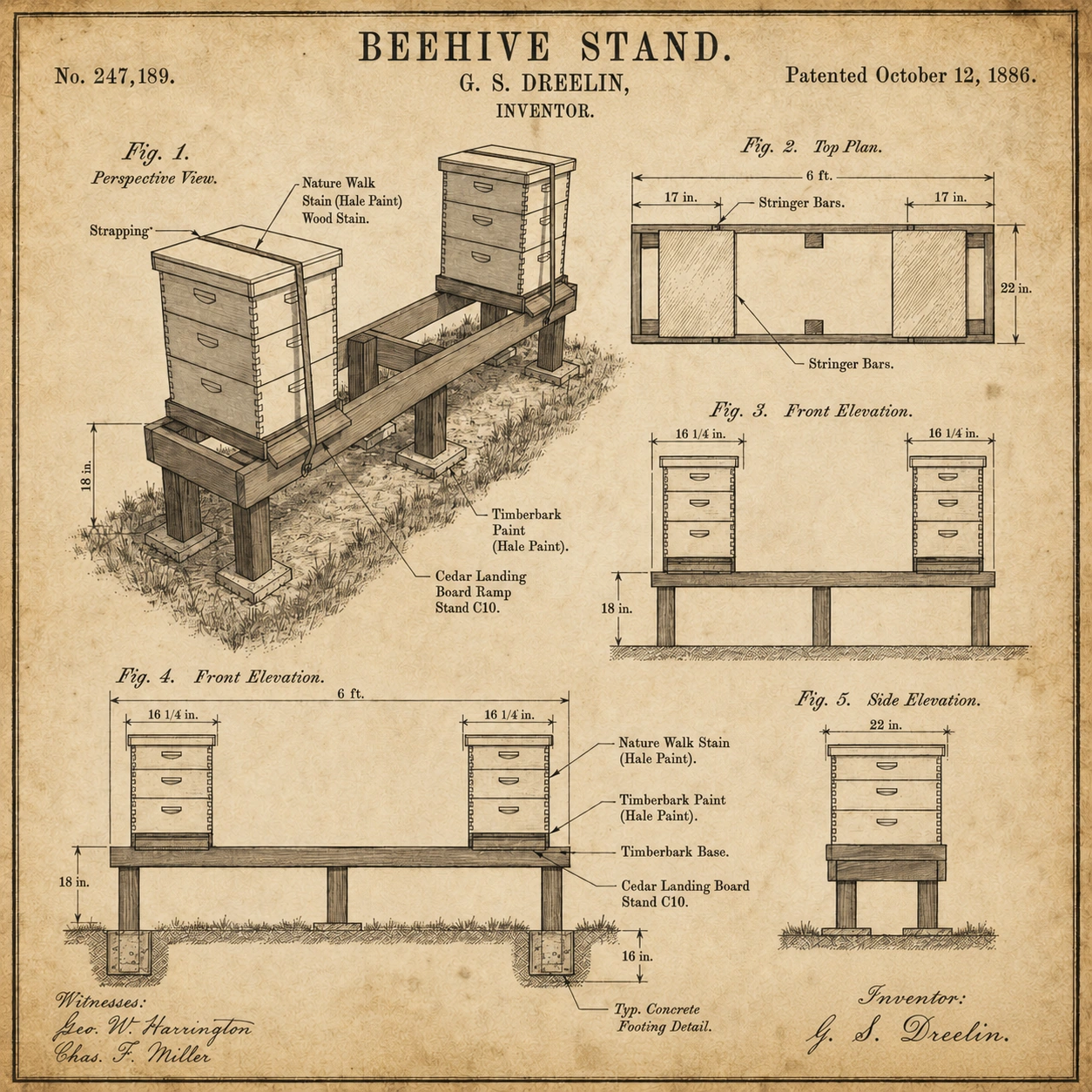
We have two of these stands at Misty Mountain Homestead, and this design has worked well for our needs. Ours use posts that extend into the ground with concrete around them, with the top of the stand’s frame 18 inches above the ground. The long, open frame gives two hives their own places and leaves a useful gap between them.
Here is a practical way to build that style of stand, with our vintage-style project illustration for inspiration and two construction sheets to help you picture the parts.
Simple lines. A steady home.
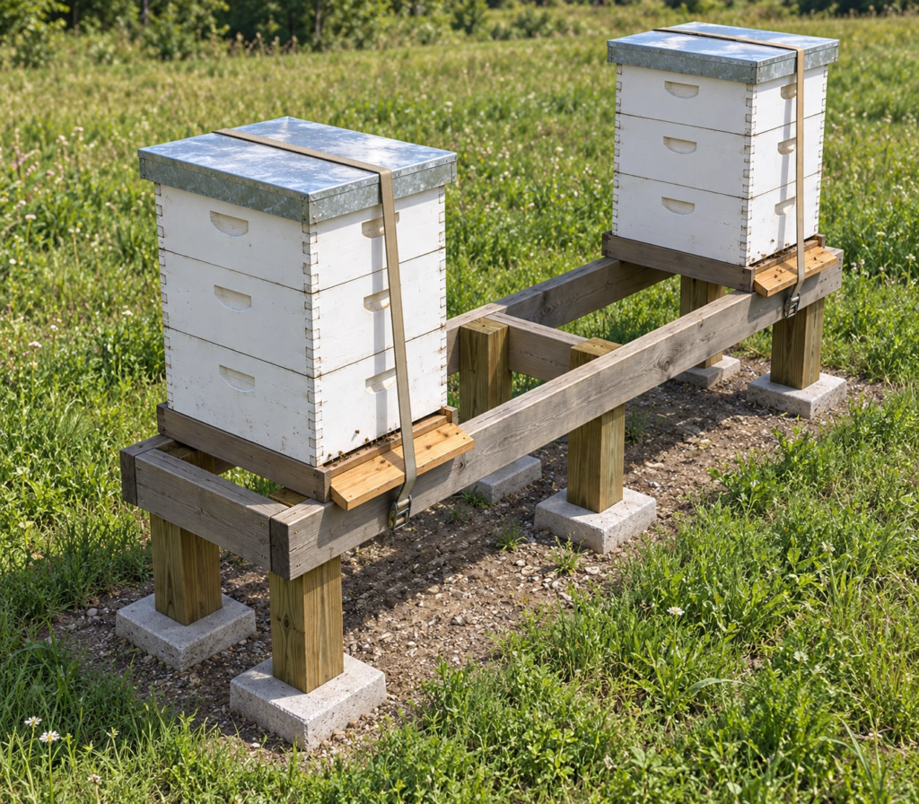
The stand is an open rectangle: two long rails joined by crosspieces, with three pairs of posts beneath the rails. Each hive sits near an end, close to the end supports. The center stays open; it is not a walking platform or a seat.
Start with the boxes you actually own
The supplied drawings show hive widths around 16¼–17 inches and a 22-inch depth. Treat those as reference dimensions, not a promise that every bottom board will match. Measure the bottom boards, entrance projections, screens, and any landing ramps before cutting lumber. Make sure the intended bearing surfaces are supported and the entrance and ventilation stay clear.
Gather the parts. Settle the measurements.
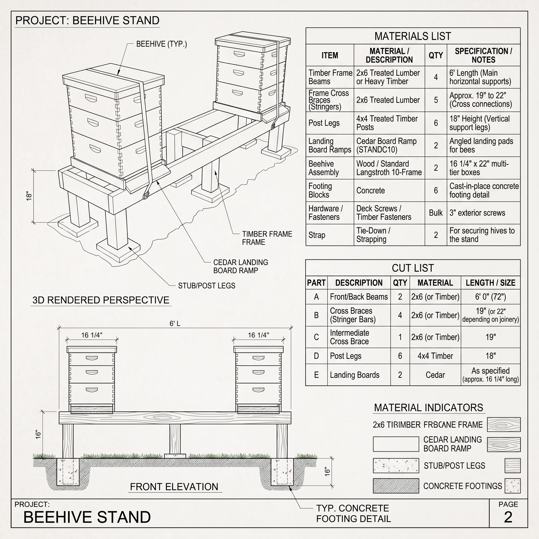
The cut list below describes one consistent frame option: two single-thickness 2×6 rails, five 2×6 crosspieces fitted between them, and rails bearing directly on six post tops. It follows the 72 × 22-inch frame footprint shown in the drawings.
| Part | Quantity | Material & cut |
|---|---|---|
| Long rails | 2 | 2×6 lumber, each 72 inches long |
| Crosspieces | 5 | 2×6 lumber, each 19 inches long for this between-rail layout |
| Posts | 6 | Ground-contact-rated 4×4 posts; length depends on embedment, frame height, and site grade |
| Landing ramps | 2, if needed | Cedar or compatible hive equipment; size to your actual bottom boards |
| Post-to-rail connections | 6 locations | Connectors approved for the selected 4×4-to-2×6 bearing detail, with their specified fasteners |
| Crosspiece connections | 10 ends | Rated connectors or an approved joint detail; use the specified fasteners |
| Concrete | Site dependent | For six post foundations, sized for the soil, embedment and intended load |
| Hive straps | 2 | Weather-resistant tie-downs appropriate to the hives and anchorage |
| Bracing & finish supplies | As needed | Temporary braces, any required permanent bracing, cut-end preservative, and optional exterior finish |
22 − 1½ − 1½ = 19 inches.
That is the clear space between two rails that each actually measure 1½ inches thick. Check the lumber in your hands. If you use doubled beams, heavier timber, or a different joint, recalculate the crosspieces.
Read the drawings carefully before buying or cutting
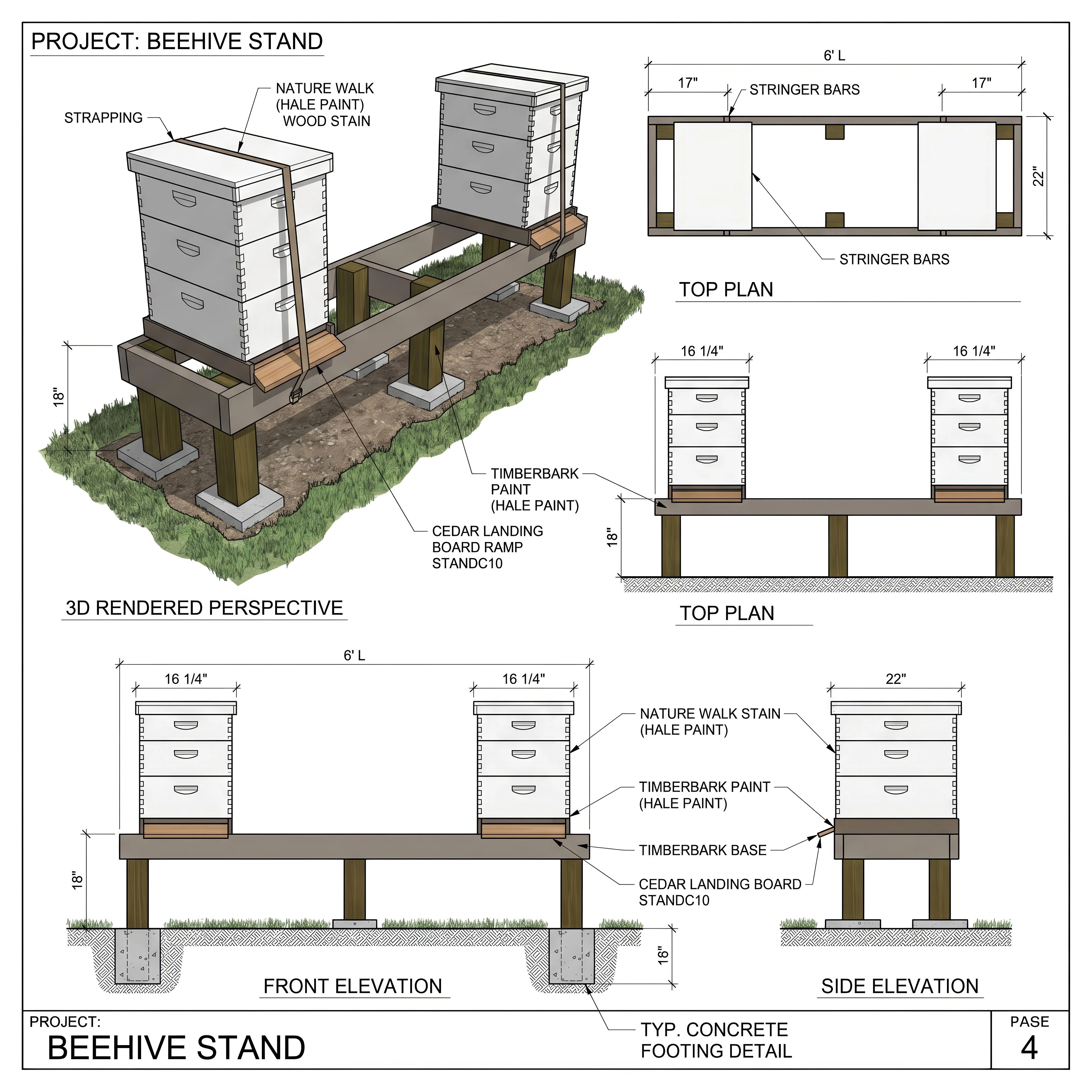
The sheets mix a few versions: the materials table lists four long beams while its cut list lists two; crosspiece notes range from 19 to 22 inches; and height labels vary. The article’s table is the reference for the single-rail frame described here. It is not a claim that every label on the artwork matches that option.
An 18-inch leg is not an 18-inch finished stand when the frame sits on top of it. For the 18-inch frame-top target, a 2×6 standing on edge adds about 5½ inches, leaving about 12½ inches from finished ground to the post-top bearing surface. An embedded post must also include its full below-ground length, plus trimming allowance. If you choose a different height or joint, change that calculation.
The 16-inch below-ground dimension pictured on the sheets is not a universal footing specification. Confirm foundation depth, hole size, post treatment, and connection details for your soil, frost conditions, and expected hive load before digging. A local qualified builder can help resolve those details.
Tools worth having close by
Tape measure, pencil, framing square, long level or laser level, string line, clamps, saw, drill/driver, post-hole tools, and concrete-mixing equipment. Use appropriate eye, hearing, dust, and hand protection for the work and products involved. Keep tools and fresh finishes away from active hive entrances.
For buried posts, buy wood rated for the actual ground-contact exposure rather than relying on an exterior paint finish. Check the treatment tag, and follow its instructions for cuts and drilled holes. The American Wood Protection Association explains the use categories and field treatment.
From a few boards to an apiary fixture.
Choose the spot and plan the dig
Pick a firm, well-drained working area with room to stand beside and behind the colonies. Think about the route you will carry boxes along, and keep the bees’ entrance flight path away from the busiest foot traffic. Allow space for the whole frame, its post foundations, and maintenance around them.
Before making holes, request a utility locate and complete the required marking process. In Virginia, Virginia 811 explains the lead time and procedure; private lines may need separate locating. Settle the site-specific foundation detail before continuing.
Dry-fit a square frame
Cut the two rails to 72 inches. For the stated single-rail option, cut five crosspieces to 19 inches. Lay the parts out on a flat surface: two end ties, one central tie, and two additional pieces positioned to support the inner edges of the hive bases.
Try the actual empty bottom boards on the layout. Adjust the two hive-support pieces to suit them rather than copying the artwork’s 17-inch marks without checking. Clamp the rectangle and compare its two diagonal measurements; matching diagonals help you establish a square frame.
Transfer the six post positions
Use the dry-fitted frame as a layout reference. Mark three support stations along its length: near each end and at the middle, with a post under each long rail at every station. Keep the end hive positions near their supporting post pairs.
Locate each post so the selected connection provides full, direct bearing beneath the rail. Check that post faces and hardware will not obstruct the crosspieces or hive bases. Temporary layout stakes and string lines help preserve the rectangle while the frame is moved aside.
Set the posts in concrete
Excavate the six foundations to the site-appropriate detail you have established. Start with posts long enough for their embedment and the eventual bearing height; do not cut six 18-inch stubs from the drawing’s materials note.
Position the ground-contact-rated posts, check the spacing against the frame, and brace each one plumb in both directions. Place and consolidate the concrete according to the foundation detail and concrete manufacturer’s instructions. Shape exposed tops to shed water away from the wood where the detail allows. Keep the posts braced while the concrete cures.
Leave the stand unloaded until the specified cure period is complete. A surface that feels hard is not, by itself, a reason to put full colonies on it.
Establish a common bearing height
After curing, mark a level frame-top line from your chosen finished-ground reference. Work down by the actual rail depth to establish the post-top bearing line. For an 18-inch frame top with 5½-inch-deep rails on top, that bearing line is 12½ inches above the reference grade.
Use a level or laser to transfer the line across all six supports; sloping ground can leave different amounts of post exposed. Trim carefully and treat fresh cuts as directed for the wood product. Account for any connector thickness that changes the bearing elevation.
Seat the rails and complete the frame
Set the long rails on the post tops and install the chosen post-to-rail connectors with their specified fasteners. The post tops carry the vertical load; fasteners keep the assembly connected. Avoid substituting a few ordinary deck screws through a rail into a post side for a properly supported bearing detail.
Install the five crosspieces using the selected connection detail. Recheck the diagonals, the rail spacing, and the level as you work. Add any permanent bracing the connection design requires. The assembled frame should not rack or sway before a hive is placed on it.
Fit the landings and dress the wood
Check the empty hive bases one more time. Add the cedar landing ramps only if they suit your bottom boards and entrance arrangement. They are not the primary support for the hive boxes.
Ease sharp edges and remove protruding fasteners. If you finish the stand, use a suitable exterior product and let it dry or cure as its label requires before placing the colonies. Follow separate hive-equipment guidance for coatings; do not carry the stand’s finish into hive interiors or honey-contact areas.
Place the hives and secure the stacks
Start with empty equipment to check support, access, and clear entrances. Keep the hive bases level side to side; follow your bottom-board manufacturer’s instructions for any front-to-back drainage tilt rather than introducing a twist into the stand.
Move occupied hives with an appropriate beekeeping plan, protective equipment, and enough help for safe lifting. Fit a weather-resistant strap to each stack and its intended anchorage without blocking entrances or ventilation. Straps secure the hive; they do not replace sound foundations, bearing, and frame connections.
A closer look at the construction.
Open either image for the full-size sheet. Use the article’s reconciled cut list and site-specific foundation details alongside these references.
The final walk-around.
- Concrete has completed the specified cure period.
- All six posts are sound and the frame is square, connected, and steady.
- Rails bear fully on their supports; no hive relies on a landing ramp.
- Bottom boards fit without rocking, blocked screens, or obstructed entrances.
- Hardware is complete and compatible with the treated wood.
- Hive straps and lifting access are ready.
Recheck the stand after the first loading, after severe weather, and as part of regular apiary maintenance. Look for movement, loosened connections, corrosion, damaged straps, and decay near the ground line. Address changes before stacking on more weight.
Project notes & further reading
Project illustrations supplied by Misty Mountain Homestead. The vintage-style sheet is artwork; its decorative patent-style text is not presented here as a verified historical patent. Dimensions in this article describe the stated construction option, rather than a certified structural plan.
- Mississippi State University Extension: Beginning Beekeeping in Mississippi — context on hive equipment and full-box weights.
- American Wood Protection Association: treated wood use categories and cut-end treatment.
- Virginia 811: what to expect before digging.
There’s always another story.
Keep exploring the garden, the barnyard, and the kitchen.
Read the journal ↗